Technical note
Why soft switching cuts EMI at the source
Electromagnetic interference is the tax a switching converter pays for being a switching converter. The usual reflex is to pay it downstream, with bigger common-mode chokes, more filter stages, and shielded enclosures. That works, but it treats the symptom. It is worth understanding where the noise actually comes from, because the answer points to a cheaper fix.
The noise is in the edges, not the frequency
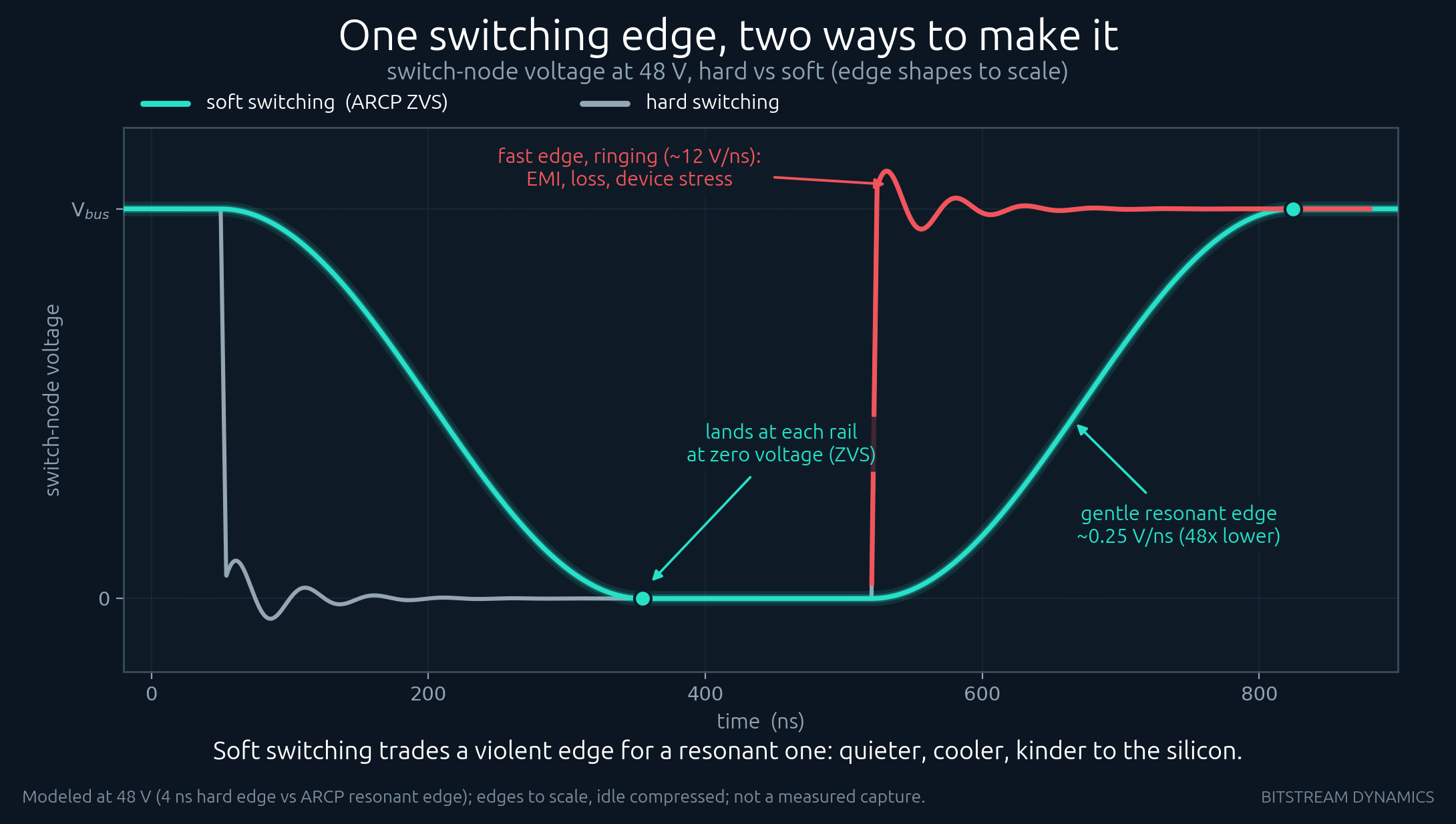
People often assume the trouble is the switching frequency itself. It is not. A converter running at 100 kHz does not radiate most of its energy at 100 kHz. The high-frequency content that breaks conducted-emission limits, up in the tens of megahertz, is created by the edges: how fast the switch node slews, and the ringing that a fast edge excites in the parasitic inductance and capacitance around it.
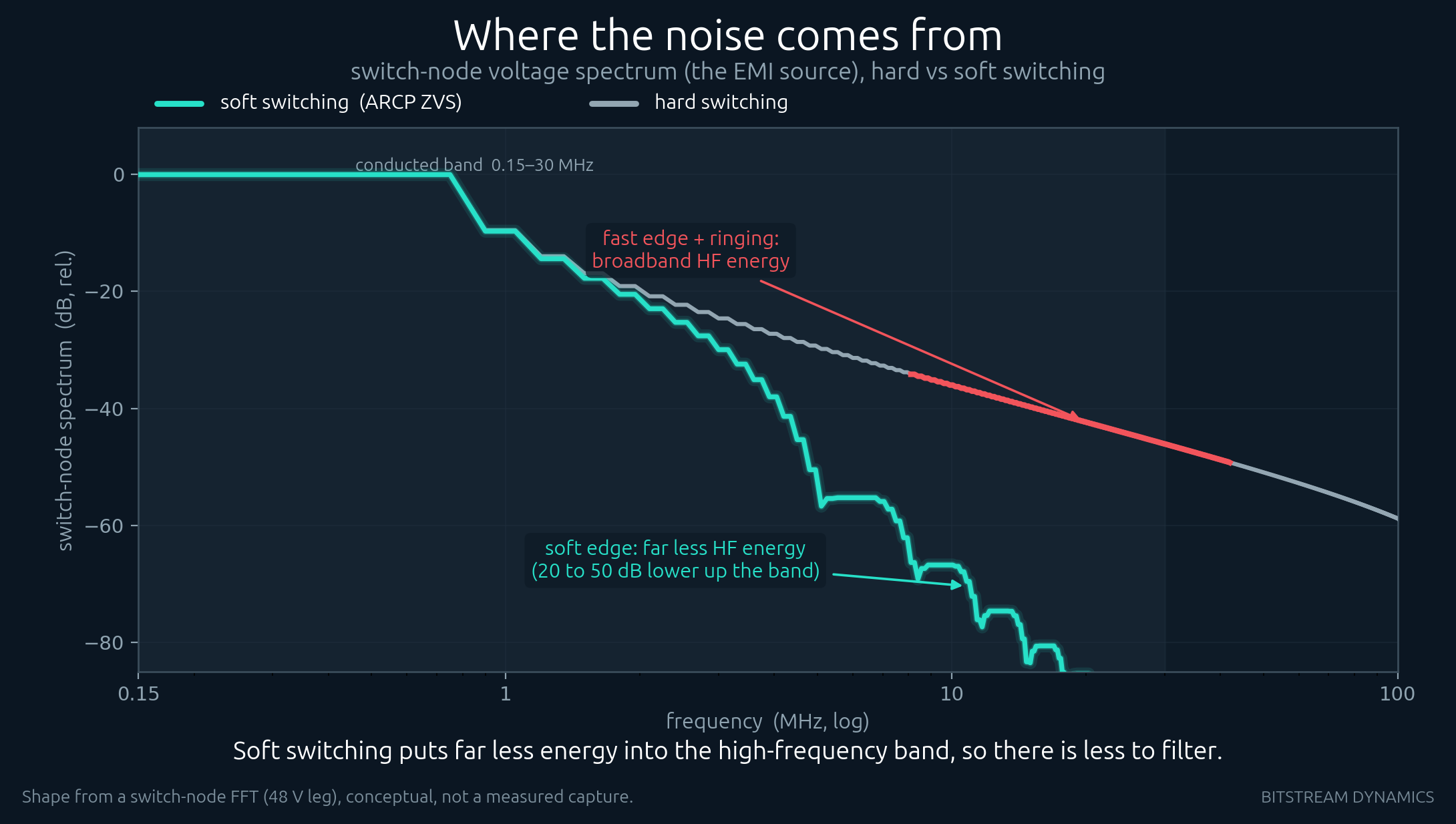
A hard switch forces the node from one rail to the other while current is still flowing. The transition is deliberately fast, because a slow one burns energy as heat. Fast means high dv/dt, and high dv/dt means broadband high-frequency energy, plus overshoot that rings for many cycles after the edge. That ringing is what forms the broadband hump that fails compliance.
What soft switching changes
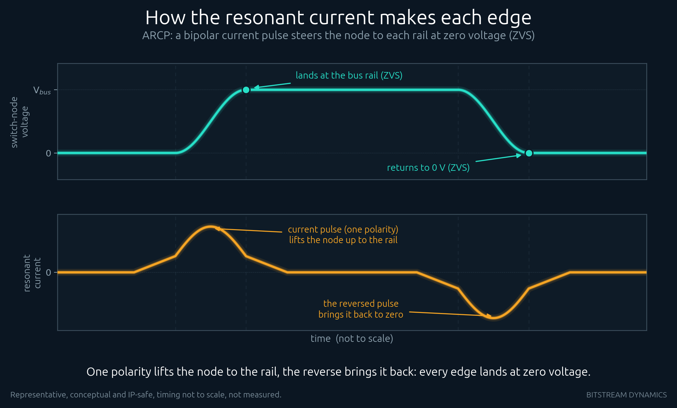
Soft switching brings the switch node to the rail resonantly before the transistor turns on, so the device changes state when the voltage across it is already near zero. There is no forced, current-carrying fast transition to create the high-frequency edge in the first place, and far less overshoot to ring. You are not filtering the noise away after it is made; you are declining to make as much of it.
The payoff shows up at the top of the spectrum, where it is hardest to filter. In our switch-node FFT model the high-frequency content drops by roughly 30 dB at 10 MHz and 50 dB at 30 MHz, widening with frequency as the gentle resonant edge rolls off about 6 dB per octave faster than a hard one. Two honest qualifications on that number. It is the source spectrum read as a peak, ahead of any filter, and a compliance scan measures quasi-peak at the equipment terminals instead. In the complete drive cases we have quantified end to end, the advantage that survives both effects lands in the 19 to 43 dB range. That is still the difference between passing with margin and redesigning a filter, and it comes with smaller filters and less voltage stress on the semiconductor and the motor insulation.
The honest caveat
Soft switching is not magic across the whole spectrum. It does not reduce the low-order switching harmonics near the fundamental switching frequency; those are set by the modulation, not the edge. What it targets is the high-frequency edge and ringing content, which is exactly the part that is expensive to filter and hard to pass. If your compliance problem is low-frequency, soft switching is the wrong tool. If it is the broadband HF hump, it is often the cheapest tool you have.
Fighting an EMI problem in a motor drive?
A diagnostic sprint tells you whether the fix is soft switching, layout, gate drive, or something else, before you redesign a filter. Start one.